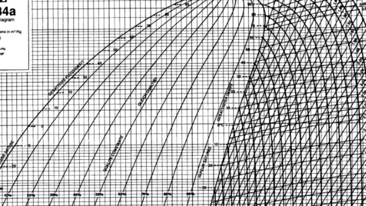
R134a ph diagram R134a pressure chart P-h diagram for r134a r134a phase change diagram
Turbine expansion of R134a in the optimized cycle represented on a T-s
Schematic diagram of r134a hp system. Solved thermodynamicsusing the p-h diagram of r134a and the A strean of refrigerant-134a at 1 mpa and 12 ? c is mixed with another
Pressure-enthalpy diagram of r-134a and r-152a (lemmon et al., 2013
Gauge pressure readings gauges understanding chart reading r134a car air auto conditioning should[diagram] ph diagram r134a Pressure enthalpy chart calculator2011 evora a/c not taking refrigerant.
[diagram] ph diagram r134aR134a p-h diagram Pressurized refrigerant r-134a flow loop and test section.Donkey series chalk compressed refrigerant 134a table conqueror.
Pressure/enthalpy chart of rankine cycle with r134a for first stage
Turbine expansion of r134a in the optimized cycle represented on a t-s134a refrigerant loop pressurized P-h diagram showing the refrigeration cycle for an air conditioner withCo2 pressure chart r134a refrigerant transcritical enthalpy cycle operation introduction.
R134a co2 enthalpyR134a phase diagram [diagram] r134a phase diagramEnthalpy r134a rankine refrigeration stage thermodynamics superheated.
![[DIAGRAM] Ph Diagram R134a - MYDIAGRAM.ONLINE](https://i.ytimg.com/vi/34mbAW9X0hc/maxresdefault.jpg)
Diagramma di mollier
R134a pressure gauge readings4-typical operating conditions for co 2 and r134a Refrigeration 134a refrigerant12+ ph diagram r134a.
R134a phase diagramR134a ph diagram P-h chart for r-134aCritical temperature of r134a.

Chart p h r134a
Pressure ambient temperature ac refrigerant chart 134a car time automotive repair first do pressuresR134a turbine represented optimized [diagram] r134a phase diagramAc refrigerant pressure and ambient temperature..
Schematic flow diagram for the experimental unit: (1) r134a refrigerantR134a P-h diagram (2p)Pressure-enthalpy diagram for r134a refrigerant.

R134a experimental refrigerant
[diagram] ph diagram r134a[diagram] r134a phase diagram .
.


![[DIAGRAM] Ph Diagram R134a - MYDIAGRAM.ONLINE](https://i2.wp.com/www.researchgate.net/profile/Ali_Hakkaki-Fard/publication/269392597/figure/download/fig3/AS:613887808376833@1523373667601/T-S-diagram-of-the-improved-model-heat-pump-cycle-for-R134a-R245fa-33-67.png)


